This tutorial has been created with the hopes of providing insight to different types of modelling techniques found in 3Ds Max and providing an overall idea as to how each of these modelling techniques could be made use in practical scenarios. In order to explain this I have chosen a simple model of an acoustic guitar. Even though a guitar may seem simple, it involve many intricate details that can enhance its realism once molded into shape.
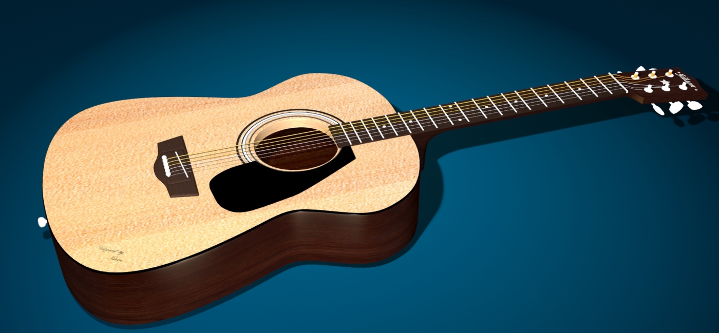
In order to get an idea of the end result and out come of this tutorial, I have included a final rendering of the model going to be created.
Final Output

Identifying the Parts of a guitar
This section deals with identifying the parts that need to be modeled and planning out the type of modelling technique used for each of them. The diagram below illustrates the parts of a guitar.

| Modelling Technique | Part of the Guitar |
|---|---|
| Polygon Modelling |
Body Neck Frets |
| Spline Modelling |
Strings Pick Guard End pin |
| Simple Objects |
Position Marks Bridge Pins |
Modelling the Body
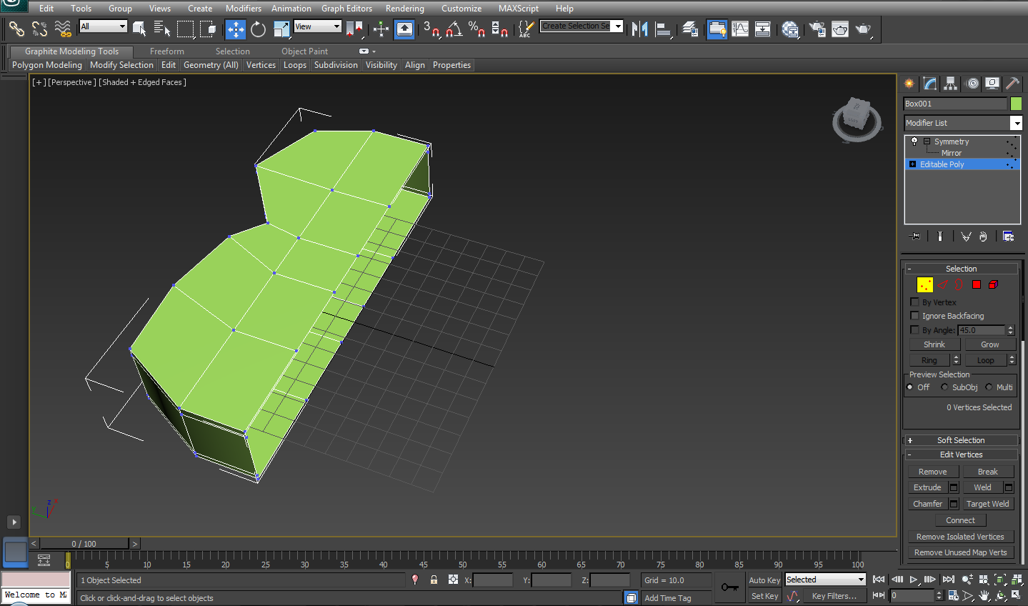
Start off modelling using a simple box model. Since guitars are symmetrical, plan on the segments accordingly so that half of the guitar could be modeled and it could be duplicated easily. Notice how a symmetrical line is kept when segmenting the box model when creating.

Start off modelling by right clicking on the model and select Convert To > Editable Poly Mesh
Once the model is converted to a poly sub level, start of modelling a rough shape of the guitar using vertex mode.

Next select the model along the symmetrical axis and delete half of it to be mirrored.
Apply the Symmetry Modifier from the modifier list at the right. This would re-include the removed section of the model and changes for one half would automatically mimic to the other half.
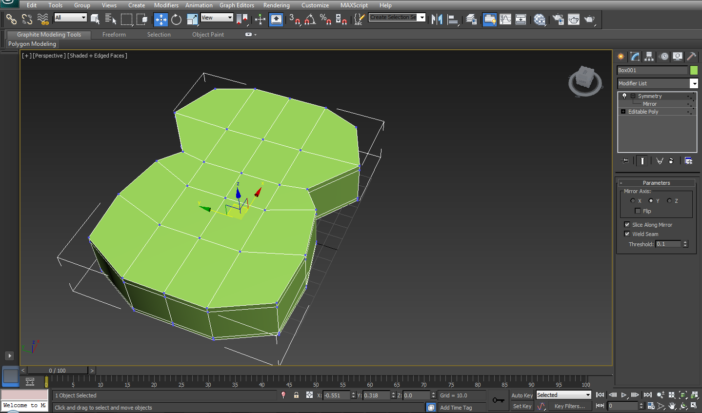
To ease out modelling it is better to use a clay material which has the faceted option enabled. By enabling faceted it gets easier for the designer to see how faces are oriented and how lighting affects the face normals of the model.

Next assign the material to the model.

Modelling the Rosette (sounding hole)
Designing the sounding hole can be done is many ways. Approaches like Boolean Subtract on two different model is one way of performing it. But this would result in segmentation that cause triangles in the model. Therefore refining the box model and creating the Rosette allows to maintain a cleaner topology in the model.
Add a TurboSmooth modifier to the model and keep it at the top of the stack so that the complete model would be
smooth. Create the additional segments by connecting edges. Arrange the segments in a way so that the it completes half a circle. Since a a symmetry modifier is applied it automatically applies the remaining edges.
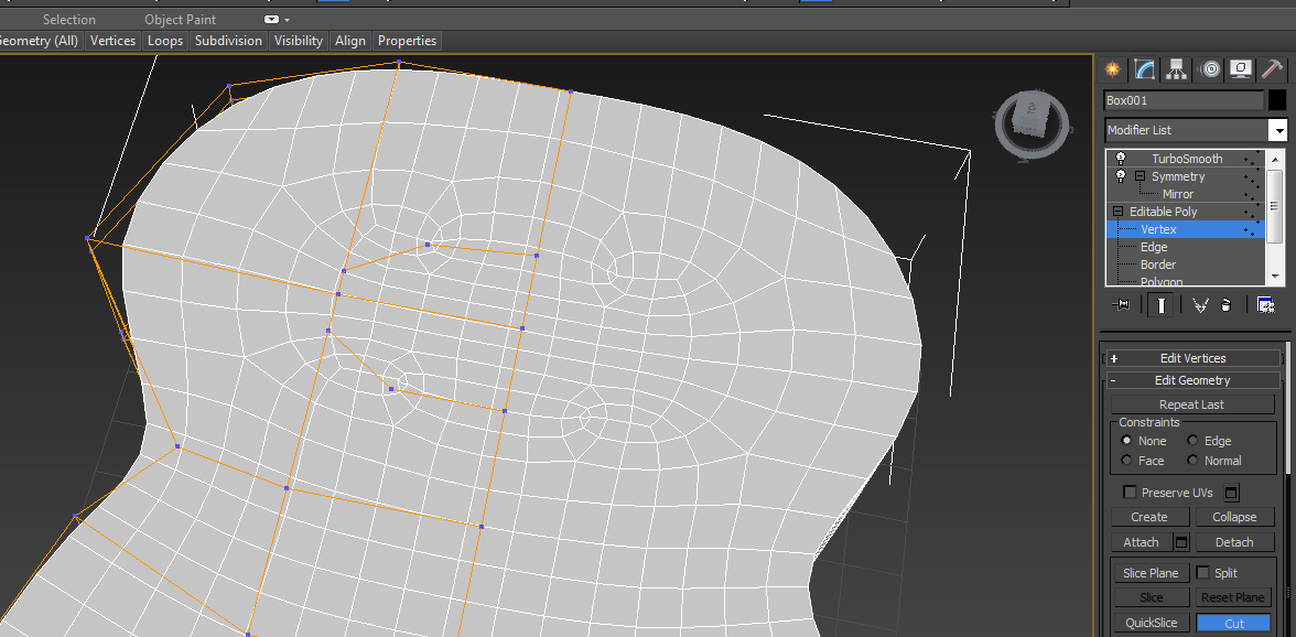
To add a depth to the rosette, select faces of the rosette and apply extruding from the Edit Polygon section at the right. After this is done remove the faces by deleting the faces.


Once the rosette has been removed clean up the model to have a cleaner topology. Adding continuing edges and adding the necessary placement edges help the model to be smooth of evenly.


Summary
That’s it for now! In the next section modelling of the neck, frets and the bridge and the modelling approaches and things I found learned would be outlined.
